
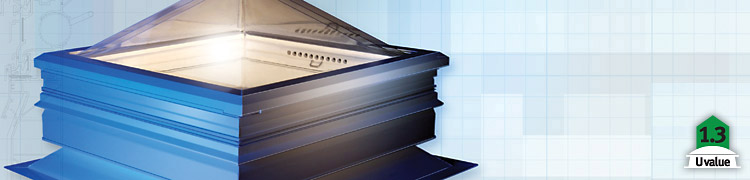
X-One Rooflight—The Lowest U Value
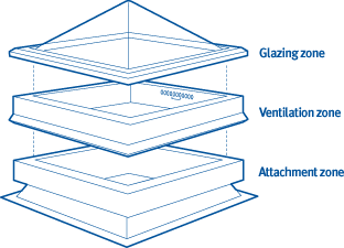
With an exceptionally low U value of 1.3, exceeding Part L requirements, this model from Xtralite represents the future of rooflights. The X-One also benefits from high thermal performance. Unlike other rooflights, the X-One rooflight is designed and constructed in three distinct zones to clarify specification and maximize performance and flexibility (see diagram below).
Waterproof Rooflight Glazing System
The X-One is triple glazed as standard and formed from enhanced UV protected polycarbonate with breathing airspaces between the glazing elements. The integral cascade water management system ensures that moisture drains to the outside of the building removing risk of leakage.
Rooflight Accessory Frame
The rooflight accessory frame is the key element which ensures Part L compliance and gives X-One its unique environmental efficiency. The frame is constructed from a single, highly complex, PVC profile designed to efficiently ‘dock’ between the glazing module and either the kerb adaptor profile or the kerb, creating a secure, weathered and warm connection with no cold bridges.
The accessory frame arrangement is flexible depending on the specifiers requirements. For example it can include a unique continuous hinge manual or electrical opening, allowing for high volume air ventilation.
This allows for high-volume air ventilation. A PVC extruded profile rotary ventilator system can be mounted in the sidewall of the accessory frame. The cylindrical profile protects it from the outside elements using a continuous cowl feature and integral insect mesh. The vent design ensures that no cold bridging occurs between the outer and inner surfaces. When the vent is closed it forms a virtual triple skin chamber with very low air leakage and exceptional sound reduction performance. The ventilation system is simply operated by rotating the operating handle.
Flexible Rooflight Attachment
Xtralite have developed unique rooflight mounting systems to aid attachment and make the process of incorporation easy.
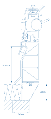
A versatile metal foot will allow for a variety of thicknesses of roof insulation, whilst allowing ‘flexible’ matching of rooflight to roof opening as well as ‘cut to falls’ variable depth insulation systems.
Fixing direct to the roof deck allows for the kerb to be attached direct to the supporting structure which could be above the insulation layer or by using a kerb adaptor direct to any pre-constructed builders kerb.
The kerb has three main insulating chambers ensuring compliance with Part L regulations and with projected future changes, by the addition of high performance insulation to the chambers. The kerb is designed to be equally suitable for, and compatible with, both polymeric and PVC roofing membrane systems, bituminous membrane and mastic asphalt systems.
The rooflight assembly includes a unique termination detail to ensure that the ‘top edge’ of the roofing membrane is fully protected. A special ‘key’ finish to the PVCu kerb increases roof membrane fixing options and the PVCu kerb torch-on system friendly. Simplified assembly allows the roofing finish to be applied to the upstand prior to clipping the Glazing Section and Ventilation Frame into position. This procedure minimises damage and the need for protection, and eliminates dressing around the vents.
|
How to specify Xtralite rooflights |
If you need to know more about the elements that make up the X-One rooflight, click on the following for more information: Understanding glazingUnderstanding ventilationUnderstanding roof fixing and security |
If you would like to specify exactly which X-One configuration you require, click on the following to go to the specification guide: Go to specification guide |
To find a full range of PDF and CAD drawings for the Xtralite range, click on the following to go to the downloads section: Go to downloads section |
The U value of a rooflight is calculated by dividing the heat transfer across the system (measured in Watts) by the environmental temperature difference across the test element (measured in degrees K) multiplied by the area of the aperture in the surround panel—called the projected area (measured in m²). This latter dimension is equivalent to the opening in the building envelope. One consequence of this is that the ‘U’ value of the product will increase as it gets deeper, despite the thermal properties of the individual components staying the same.
The building energy software SBEM uses the actual area (often called the developed area) of the product, to calculate the heat transfer through the product.
To show what this value is, a “supplemental” U value has been calculated using developed area and it is this relevant value that we quote in this document. |